Challenges in Core Shell Brown Field Project: A Case Study
By Ar.Prasanna Wategaonkar
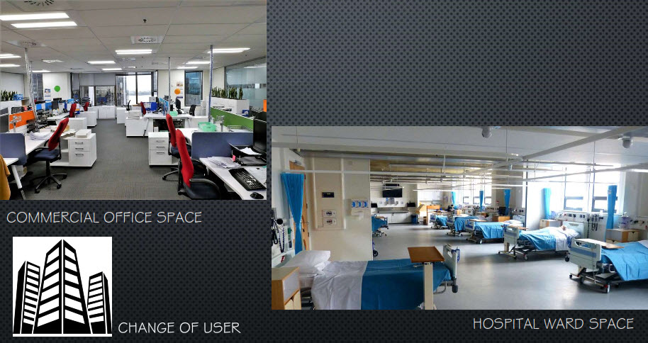
Brownfield projects are always tricky as one has zero control over the structural and archi-tectural planning. Hosmac’s Interior Designer Prasanna Wategaonkar tells us how his team converted an IT Park in tier II town of Maharashtra to a 350-bedded corporate hospital.
The Original Building
The building was designed as an IT park with basement, ground, mezzanine and 5 upper floors.
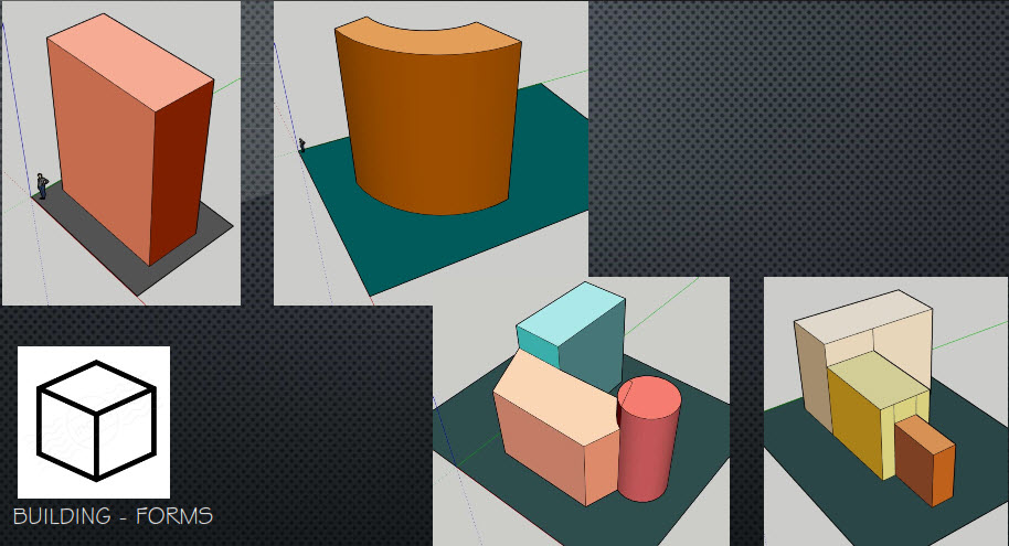
Form of the building: Curvilinear
Width: 28 m
Length : 115 m
Total Buildup Area (BUA) : 2.7 lakh sq.ft (after addition of two more floors)
Structural Design: The structure is designed with Post Tension slab (PT slab) and beam patterns, where tendons are placed radially in accordance with its geometry. The minimum distance between two tendons is 300 mm towards radial centre and 700 mm at outward periphery.
Challenges
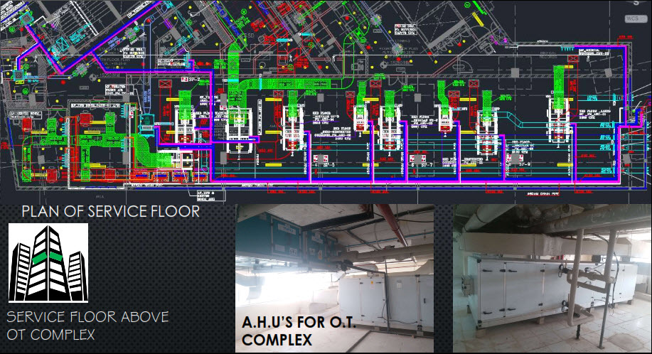
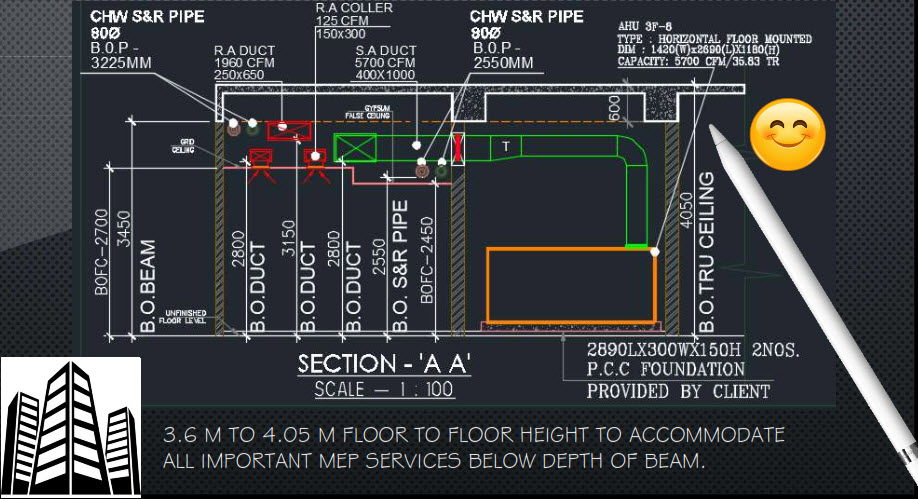
The structure has adequate height in all floors except mezzanine. The central lift shaft was of inadequate size i.e. it did not have space for stretcher or bed lift as per hospital design requirements. Furthermore, the main fire escape staircase was 1200 mm wide, which according to Fire NOC mandate needs to be 2000 mm wide (at least).
The foremost challenge was to add additional lift shafts and wider staircases at both ends of the arc. It was a new construction with expansion joint to existing structure. Equally challenging was to convert staircase width from existing 1200 mm to 2000 mm. The structural engineers had not kept extra floor rise arrangements for future expansion. However, according to space programme, two additional floors were required above existing building.
Fixing structural design challenges in a brownfield project are always a Herculean task, as it is the engineering is in accordance to the initial structure, not foreseeing future transformation.
Due to PT slab, the Uniform Distributed Load (UDL) was designed as 200 kg/sq. m; however hospital design guidelines requires this figure to be 400 units, as minimum. Hence, dry walls was the only option for modification; wet walls are built only for wet areas such as toilets, dirty utility, etc. To achieve UDL of 400 kg/sq. m, we decided to strengthen the slab from bottom with MS fabricated beams at equal intervals, running radially towards centre of the arc. This was an additional load over existing columns and beams of the super structure; as a result central columns started buckling and could not resist additional load. thus structural designer suggested to wrap columns with carbon fibre fabric for seismic strengthening. At last, structural design challenges were successfully sorted out; meanwhile schematic designs were approved and site was ready for execution. MEPF contractor team lined up with schedule of completion.
However, there were many challenges at site that were unforeseen. Midway to the renovation, it was detected that core cuts shown in floor plate were not possible. The reason: in hospital design, under plumbing services, there are instances when essential wet areas close to the department are needed and often it directed inwardly rather than outward. Being a PT slab core, cuts at defined location were possible with respect to tendon lines only, and not randomly. It was only while making the essential core cuts, that it was discovered that tendon line (normally red in colour) was off centre in a few areas i.e. not exactly in line with tendon. The core cut agency refused the assignment unless exact location for cutting was located. The Hilti team came to the rescue to scan essential areas and detect tendon position and mark locations of core cuts between two tendons. To make matters less complicated, it was unanimously decided that most wet areas will shift to exterior (outward) periphery. The wet area were raised above slab to take drain lines underneath it and connected to nearest vertical shaft of the exterior façade. The floor plans had to be revised again to ease out complicated plumbing works.
While plotting departmental internal walls at site, none of the approximately 850 rooms had all four walls that are were at right angle to each other. Each room has its own geometry (since the building form was curvilinear); thus cementing floor tiles (which are usually squares and rectangular in shape) was tricky as well. The existing centre staircase in RCC were also demolished and replaced with a new one (in RCC as well) with 2000 mm flight width all the way from basement to terrace.
Finally, all foreseen and unforeseen hurdles were crossed. The building was recently inaugurated as 350 bedded multi-specialty hospital in West Maharashtra.
Author : Ar. Prasanna Wategaonkar has over two decades of experience in architecture planning and design, and interior design. He has extensively worked on conceiving his detailed design sketches to develop, construct and manage varied projects in multiple sectors including residential, industrial, IT malls, parks and multiplexes.


